INA226 — i2c address & wiring
16-bit current, voltage and power monitor — high- or low-side, up to 36 V.
Key facts
INA226 at a glance
| i2c address | 0x400x410x420x430x440x450x460x470x480x490x4A0x4B0x4C0x4D0x4E0x4F address-selectable via pins/jumpers |
|---|---|
| Logic voltage | 2.7–5.5 V |
| Type | adc |
| Part | TI INA226 |
| Ships with | generic modules — plain 0.1″ headers, no connector system |
| Datasheet | TI INA226 — manufacturer documentation ↗ |
The chip
What the TI INA226 actually is
Precision power monitor measuring shunt voltage (±81.92 mV full scale), bus voltage to 36 V and internally computed current and power, on either the high or the low side. 16-bit resolution, programmable averaging and conversion times, and an ALERT pin for over/under-limit interrupts — the step up from the INA219 in resolution and flexibility.
Watch out: The '15 A / 20 A' module listings hide the maths: the chip's ±81.92 mV shunt range means maximum current is set entirely by the shunt fitted. An R100 shunt caps you at 0.8 A; double-digit amps need R005 or lower. Check the actual resistor on the board, not the headline.
Wiring
How to connect the INA226
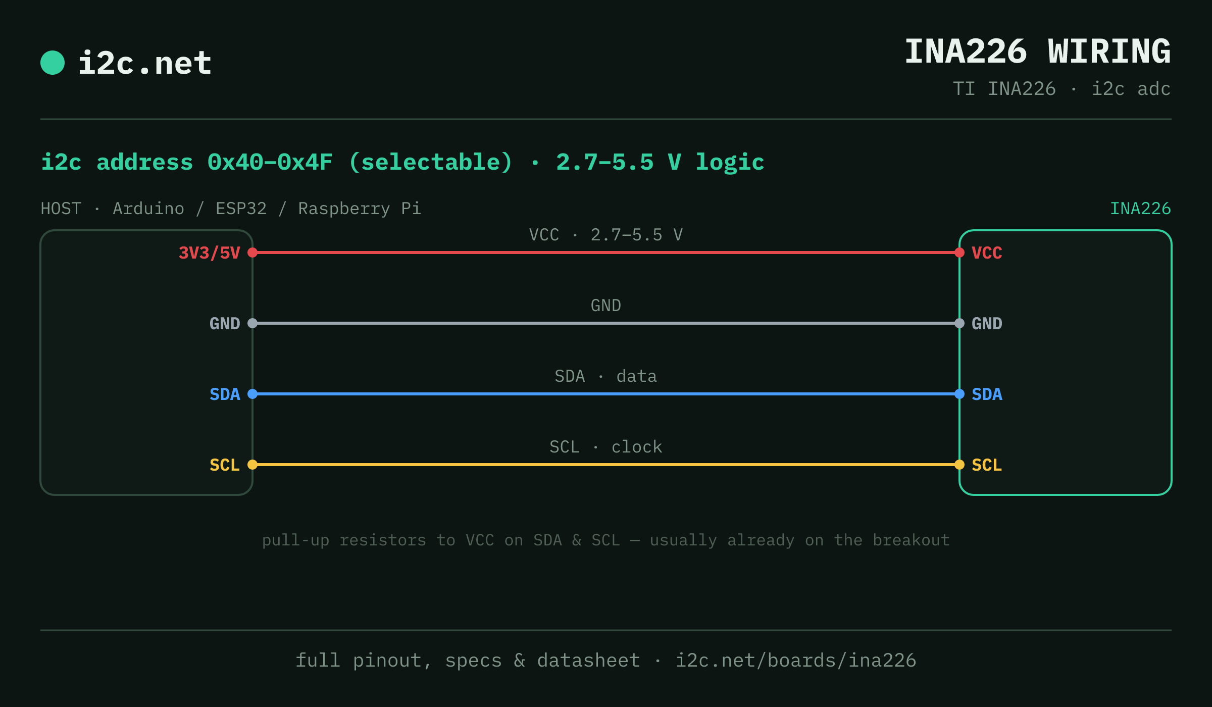
The INA226 talks i2c at address 0x40 (up to 16 selectable addresses, handy when you need more than one on the same bus). It runs at 2.7–5.5 V, so match your host's logic level — if your host is 5 V and a board on the bus is 3.3 V-only, add a level shifter. Use the compatibility checker to confirm the exact cable for your setup.
Because the address is selectable, you can run several INA226 boards on one bus by setting each to a different address — no extra wiring beyond the shared SDA/SCL.
Wiring is the usual four: power, ground, SDA and SCL, plus pull-up resistors — almost always already fitted on the breakout. Nothing showing up? Run an i2c scanner first; if the bus is silent, the 7-step checklist finds it faster than guessing.
Go deeper
Guides covering the INA226
Alternatives
Other power monitoring boards
Watch the bus
Boards that clash with the INA226
These want addresses the INA226 also answers (0x42, 0x44, 0x45, 0x4A, 0x4B), so they can't share a bus with it untouched. If one is address-selectable, strap it elsewhere; if not, the conflict guide covers the multiplexer and second-bus routes, and the collision roundup explains why a scan won't warn you.
Get one
Questions
INA226 i2c FAQ
What is the INA226's i2c address?
The INA226 uses 0x40 or 0x41 or 0x42 or 0x43 or 0x44 or 0x45 or 0x46 or 0x47 or 0x48 or 0x49 or 0x4A or 0x4B or 0x4C or 0x4D or 0x4E or 0x4F, selected with an address pin or solder jumper on the board. If a scan turns up something unexpected, our i2c address list names the usual suspect for every address.
What voltage does the INA226 run at?
2.7–5.5 V logic. That range covers both 3.3 V and 5 V hosts, so it drops onto a Pi, ESP32 or Arduino without a level shifter.
Can I use two INA226s on one i2c bus?
Yes — set each one to a different address (0x40, 0x41, 0x42, 0x43, 0x44, 0x45, 0x46, 0x47, 0x48, 0x49, 0x4A, 0x4B, 0x4C, 0x4D, 0x4E, 0x4F) using its address pin or jumper, then wire both to the same SDA/SCL. That gives you up to 16 on a single bus before you need a multiplexer.
Does the INA226 come as a plug-together breakout?
Not in the mainstream connector ecosystems — INA226 modules are generic boards with 0.1″ headers, so you'll be soldering headers and running jumper wires to SDA, SCL, power and ground.
What should I watch out for with the INA226?
The '15 A / 20 A' module listings hide the maths: the chip's ±81.92 mV shunt range means maximum current is set entirely by the shunt fitted. An R100 shunt caps you at 0.8 A; double-digit amps need R005 or lower. Check the actual resistor on the board, not the headline.