BSS138 i2c level shifter: 3.3 V ↔ 5 V wiring
Use a two-channel BSS138 bidirectional level shifter when a 5 V i2c host meets a 3.3 V-only device: one channel for SDA, one for SCL, with both grounds joined. The fix costs a dollar and two minutes once you know why the obvious shortcuts do not work.
The problem
Why i2c needs level shifting: mixed voltages break things
A chip's pins tolerate roughly its own supply plus 0.3 V. Drive a 3.3 V-only part's SDA/SCL from a 5 V controller and current floods its protection diodes — sometimes it dies instantly, more often it "mostly works" while degrading, which is worse. The trap is common because both rails are everywhere: classic Arduinos are 5 V, nearly all modern sensors are 3.3 V. Whether a given pairing needs shifting is exactly what our compatibility checker answers per connector ecosystem — Qwiic is strictly 3.3 V, while STEMMA QT boards build the shifter in.
And the shortcuts fail: voltage dividers are one-directional, but SDA and SCL both carry data both ways (SCL too — that's clock stretching). Series resistors just abuse the chip's protection diodes politely. Open-drain buses need a shifter that's bidirectional by nature.
The circuit
The BSS138 i2c level shifter: one MOSFET per line
The standard solution (NXP app note AN10441) puts a small N-channel MOSFET on each line: gate to the 3.3 V rail, source on the low-voltage side, drain on the high side, with a pull-up to its own rail on each side. Pull either side low and the MOSFET conducts, dragging the other side down; release, and each side floats up to its own voltage. No direction pin, no enable, nothing to configure — it exploits exactly the open-drain behaviour that makes i2c work in the first place.
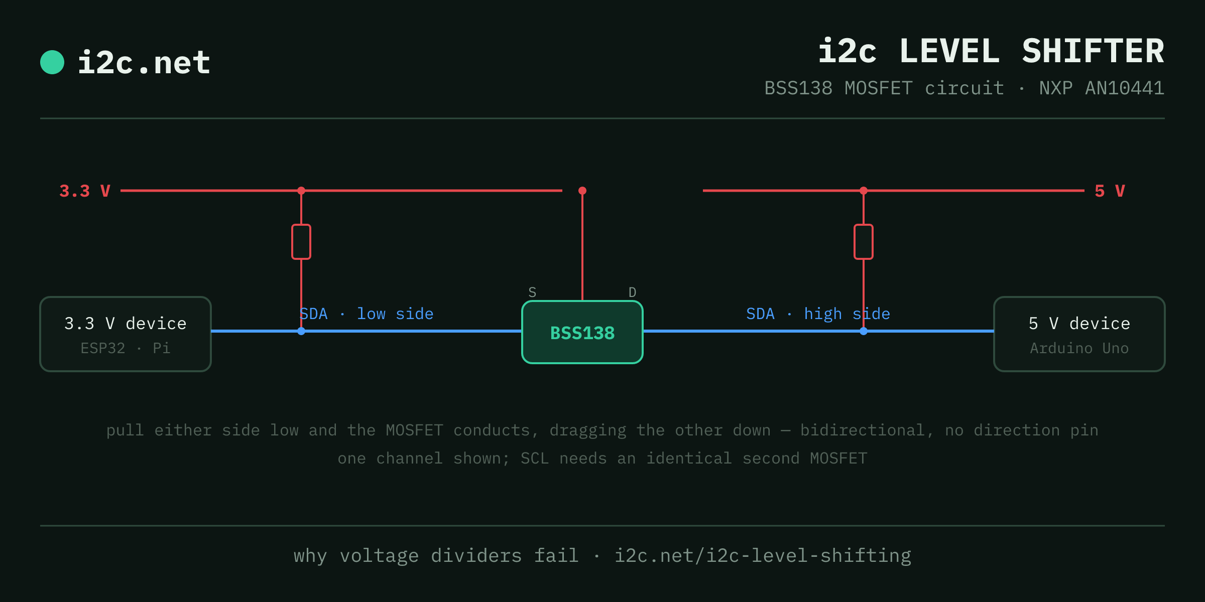
In practice you buy it as a module: 2, 4 or 8 channels of BSS138 with the pull-ups already fitted. Wiring is four connections per side plus the rule people miss — both grounds joined: LV + 3.3 V reference, HV + 5 V reference, then A-side SDA/SCL to the 3.3 V device, B-side to the 5 V device. Two of the channels do i2c; spares handle UART or GPIO.
Alternatives for corner cases: the PCA9306 is a purpose-built i2c translator rated well past 400 kHz; TXS0102-class auto-direction shifters work but their edge accelerators dislike heavily loaded buses; and for 1.8 V targets the same BSS138 circuit works with the gate on the 1.8 V rail — check the module's silkscreen supports it.
The part
Questions
Level shifting FAQ
Can I use a simple voltage divider for i2c level shifting?
No. Dividers only work for one-way signals, and i2c's SDA and SCL are bidirectional — data flows both directions on the same wire. A divider also fights the pull-up resistors and wrecks the open-drain logic levels. Use a MOSFET-based bidirectional shifter; they cost about a dollar per channel.
Do I need to level-shift both SDA and SCL?
Yes, both. SDA is obviously bidirectional, but SCL is too — clock stretching means a target can drive the clock line low. Shift both lines and connect the grounds of both sides; a shifter without a common ground reference does nothing.
When do I NOT need a level shifter?
When every device on the bus runs the same logic voltage: an all-3.3 V chain (all of Qwiic, a Raspberry Pi with modern sensors) needs nothing. Adafruit STEMMA QT breakouts also include on-board level shifting, which is exactly why they tolerate both 3.3 V and 5 V hosts.
How does the BSS138 MOSFET shifter actually work?
One small MOSFET per line, gate tied to the low-voltage rail, with a pull-up on each side. When either side pulls low the MOSFET conducts and drags the other side low too; when both release, each side's pull-up returns it to its own rail. Fully bidirectional with no direction pin — ideal for open-drain buses, which is why NXP's AN10441 app note made it the standard.
Will a level shifter slow my bus down?
Slightly — the MOSFET adds capacitance and its own pull-ups join the bus. At 100 kHz you'll never notice; at 400 kHz keep the shifter's pull-ups in your resistor math, and for Fast-mode Plus consider a dedicated translator IC like the PCA9306 instead of a generic module.