The i2c tool — scan, identify & debug any i2c bus.
Everything this site teaches, in one console utility: detect what's on your bus, troubleshoot it when it sulks, and manipulate device registers directly — with the same core scan, identify, register and multiplexer workflows on Arduino, MicroPython and Raspberry Pi.
What it does
Five i2c debugging jobs, one prompt
Scan & identify
Scans 0x08–0x77, names the usual suspect for every address it finds, then goes further: WHO_AM_I probes tell a BME280 from a BMP280, a VL53L1X from a VL53L0X, even a genuine HMC5883L from its QMC clone — twenty chips fingerprinted by ID register, not guessed — all shown in a colour i2cdetect-style grid.
See behind a multiplexer
Devices on a TCA9548A/9546A are invisible to an ordinary scan — the mux only passes traffic to channels you've opened, so eight sensors look like an empty bus. mux walks every channel and reports what's on each, listing the main bus separately so host-side chips aren't miscounted as being on all eight. c 3 then opens a channel so every other command reaches the device behind it.
Bus health & rescue
On Arduino and MicroPython, stuck-line detection reads SDA/SCL directly and the rescue command sends the 9-clock + STOP sequence that un-hangs a bus without a power cycle.
Read, write, dump, monitor
Read or write any register (multi-byte reads too), dump a chip's whole 0x00–0xFF map in a hex grid, or watch a register live — monitor mode prints only when the value actually changes.
Live bus speed
Change the clock from 100 kHz to 1 MHz on the fly on Arduino and MicroPython — no reflash — to test whether a flaky device is a speed problem before you touch a resistor.
See it work
i2c tool quick start: Arduino, MicroPython, Raspberry Pi
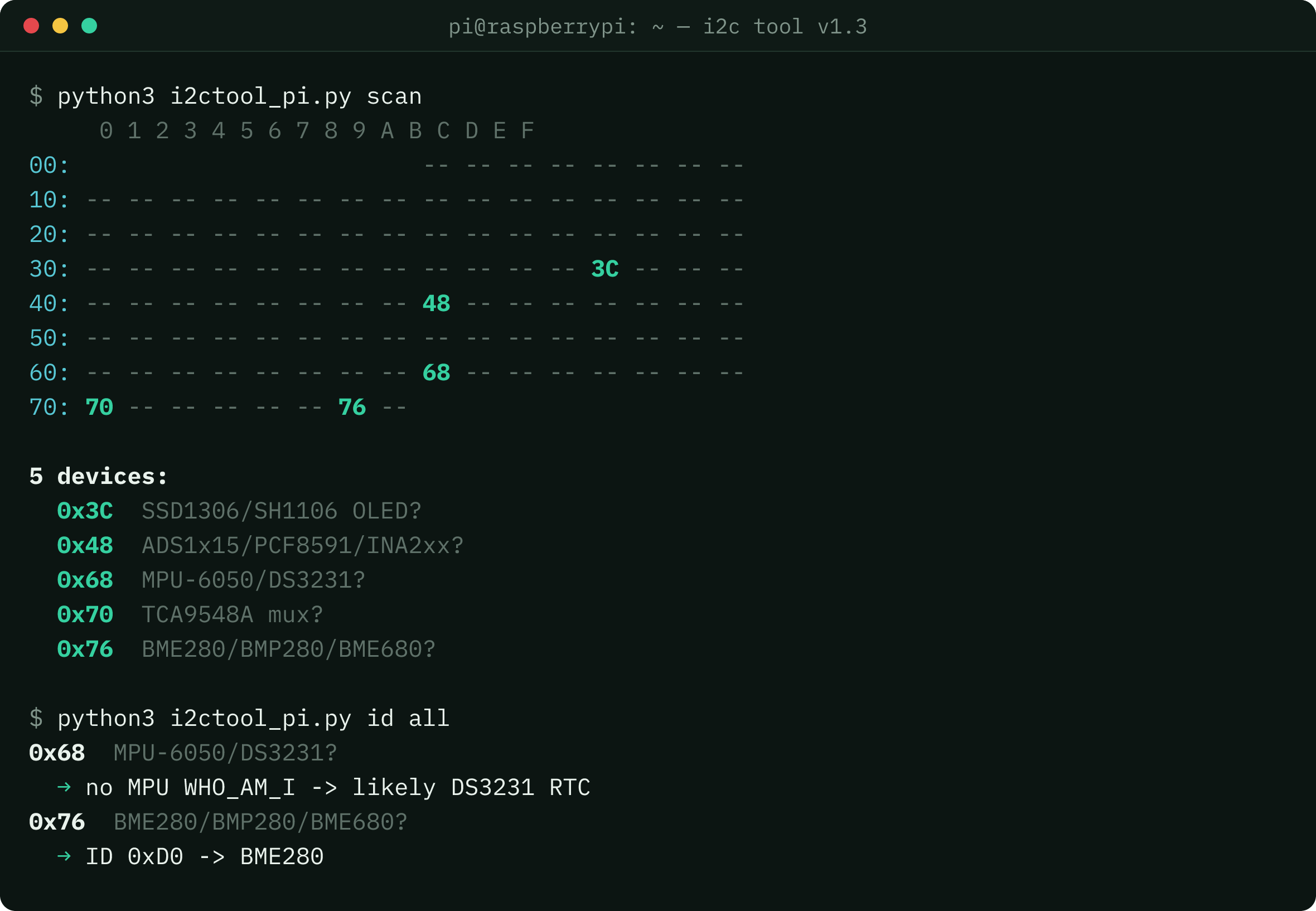
id all chip identification.Arduino / ESP32 — flash the sketch, open the Serial Monitor at 115200 baud. s prints the scan grid shown above; here's the rest:
i2c> i 76
0x76  BME280/BMP280/BME680?
  -> ID 0xD0=0x60 = BME280 (temp+hum+press)

i2c> i all
0x68  MPU-6050/DS3231?
  -> no WHO_AM_I answer = likely DS3231 RTC
0x76  BME280/BMP280/BME680?
  -> ID 0xD0=0x60 = BME280 (temp+hum+press)

i2c> r 76 F7 3
  [0xF7] = 0x5A 0x2F 0x00

i2c> f 400
  bus speed set to 400 kHz

i2c> mux
  mux found at 0x70
  main bus (all channels closed): 0x3C
  behind the mux (a 4-channel TCA9546A shows nothing on ch4-7):
  ch0: 0x76
  ch1: -
  ch3: 0x29, 0x76
  ch5: 0x68
  all channels closed. Use 'c <ch>' to open one and talk to a device.

i2c> c 3
  mux 0x70 -> channel 3 open. 's' now scans behind it; 'c' alone closes all.
MicroPython — Pico or ESP32, at the REPL:
>>> import i2ctool
>>> t = i2ctool.connect()
>>> t.scan()                     # colour grid, then the device list
2 devices:
  0x68  MPU-6050/DS3231?
  0x76  BME280/BMP280/BME680?
>>> t.identify(0x76)
0x76  BME280/BMP280/BME680?
  -> ID 0xD0 -> BME280
>>> t.identify_all()             # scan, then identify the whole bus
>>> t.watch()                    # live grid, Ctrl+C to stop
>>> t.monitor(0x76, 0xF7, 3)
monitoring 0x76 [0xF7] — Ctrl+C to stop
  [1042ms] 0x5A 0x2F 0x00
  [1243ms] 0x5A 0x30 0x00
Raspberry Pi / Linux — after enabling i2c:
$ python3 i2ctool_pi.py scan     # colour grid + device list
$ python3 i2ctool_pi.py id 76
0x76  BME280/BMP280/BME680?
  → ID 0xD0 -> BME280
$ python3 i2ctool_pi.py id all   # identify every device on the bus
$ python3 i2ctool_pi.py watch    # live grid, Ctrl+C to stop
$ python3 i2ctool_pi.py monitor 76 F7 3
monitoring 0x76 [0xF7] — Ctrl+C to stop
  [1042.3s] 0x5a 0x2f 0x00
Compatibility
i2c tool compatibility: runs on what you already have
| Arduino IDE | Uno / Nano / Mega, ESP32, RP2040 boards — serial console at 115200 |
|---|---|
| MicroPython | Raspberry Pi Pico, ESP32 — REPL module with auto pin defaults |
| Raspberry Pi / Linux | pure Python 3 CLI, no packages — talks to /dev/i2c-1 directly |
| In the zip | i2c-tool.ino · i2ctool.py · i2ctool_pi.py · README — plain source, 19 KB |
Changelog
What's new in v1.3
v1.3 — colour output and a proper interface. Scan now prints an i2cdetect-style grid with found addresses highlighted and reserved ranges dimmed, then the device list below it. A new watch mode live-refreshes that grid so you can see a device appear as you plug it in, and id all runs the WHO_AM_I probes across the whole bus in one command instead of one address at a time. Colour is automatic in a real terminal and turns itself off when piped; on the Arduino IDE Serial Monitor, which can't render ANSI, it stays off unless you switch it on with color on (use PuTTY or screen for colour there). The identify database also learns the LIS2HH12 accelerometer — the one whose address confuses everyone — and flags the TPIC2810 LED driver's 0x60–0x67 block.
v1.25 — multiplexer support, the one blind spot the tool had. Devices behind a TCA9548A or TCA9546A never appear in a normal scan, because the mux only passes traffic to channels you've opened — so a rig running eight identical sensors reads as an empty bus. The new mux command walks all eight channels and reports what answers on each, and it scans the main bus first so devices on the host side of the mux aren't listed against every channel. c <ch> opens a single channel and leaves it open, so i, r, w, d and m all work on the device behind it. Both exist because these muxes take a bare control byte rather than a register-and-value pair, so the ordinary w command can't drive one. Same feature on all three platforms: mux/c on Arduino, t.mux_scan()/t.mux_channel(n) in MicroPython, mux/ch on the Pi.
v1.2 — the identify database nearly doubles to nineteen fingerprinted chips: ENS160, APDS-9960, MCP9808, KX132, and TI power monitors told apart by die ID (INA260/INA226/INA3221, with ID-less 0x40-range parts flagged as likely INA219). A new 16-bit-register probe finally distinguishes the VL53L1X from the VL53L0X, and the tool now detects the QMC5883L at 0x0D — the clone chip most "HMC5883L" modules actually ship. Address-guess tables extended for every board in the i2c.net dataset (MAX17048, u-blox GNSS, BNO080, TPA2016, MLX90614, SH1106 and more).
v1.1 — multi-byte register reads (r addr reg n), live register monitoring with change-only output, live bus-speed control on Arduino/MicroPython (honest "edit config.txt" guidance on Linux, where the kernel fixes the clock at boot), and five more chips in the identify database: ADXL345, HMC5883L, plus wider address coverage for PCF8574, SHT31 and INA219.
v1.0 — initial release: bus scan, WHO_AM_I identify for four chip families, single-register read/write, full 0x00–0xFF dump, stuck-bus health check and rescue sequence.
Works with this site
The tool prints i2c.net references right in its output: unknown addresses point to the address list, empty scans to the troubleshooting checklist, and speed changes tie into the speed modes guide. Its scanner, identify and rescue features are the practical versions of our scanner and protocol articles — read those first if a command's output doesn't make sense yet.
Questions
i2c tool FAQ
Is the i2c tool free?
Yes — the download is unlocked by our sponsor: complete one quick offer and the download button unlocks. That's what keeps the tool and this site free.
What hardware does it run on?
Three flavours in one zip: an Arduino sketch (Uno, ESP32, RP2040 boards via the Arduino IDE), a MicroPython module (Raspberry Pi Pico, ESP32), and a pure-Python CLI for Raspberry Pi or any Linux with an i2c bus. The core scan, identify, read, write, dump, monitor and multiplexer workflows are shared; bus health and GPIO rescue are available on Arduino and MicroPython.
Is it safe to run?
Everything in the zip is plain, readable source code — no binaries, no installers, no network access, no dependencies. Open the files in any editor and read exactly what they do before flashing or running them.
Can the register-write feature damage my devices?
Writing registers is the point — it configures real hardware, so a wrong value can put a chip into an odd mode until you power-cycle it. The read, scan, identify, dump and monitor features are read-only and safe; check the datasheet before you write.
Can it see devices behind an i2c multiplexer?
Yes — that's the headline feature in v1.25. A normal scan can't: a TCA9548A or TCA9546A only passes traffic to channels you've opened, so eight sensors behind one read as an empty bus. The mux command finds the multiplexer, walks all eight channels and reports what answers on each — scanning the main bus first, so devices on the host side aren't wrongly listed against every channel. Then c 3 (Arduino), t.mux_channel(3) (MicroPython) or ch 3 (Pi) opens one channel so identify, read, write, dump and monitor all reach the device behind it.
Why can't I just use the write command to open a mux channel?
Because a TCA954x doesn't have registers. It takes a single bare control byte where each bit opens one channel, whereas the write command sends a register index followed by a value — two bytes. That mismatch is exactly why the dedicated mux and c commands exist.
What does the bus-rescue command actually do?
On Arduino and MicroPython, it is the classic recovery for a bus where a device is stuck holding SDA low mid-byte: it clocks SCL up to nine times so the device finishes its byte, then issues a manual STOP condition. The Pi/Linux CLI uses the kernel i2c driver and does not expose raw GPIO recovery.
What does monitor mode do?
It re-reads one or more registers a few times a second and only prints a line when the value actually changes — handy for watching a sensor update live, confirming a write took effect, or catching an intermittent fault without spamming the console with unchanged reads.
Can I change the bus speed without reflashing?
On Arduino and MicroPython, yes — the f command (Arduino) or set_freq() (MicroPython) changes the clock live, useful for testing whether a flaky device is a speed problem per our speed-modes guide. Linux fixes the i2c clock at boot, so the Pi version's freq command prints the exact config-file line to edit instead of pretending to change it live.
Which chips does the identify command recognise?
Twenty, by reading the chip-ID (WHO_AM_I) register where the silicon has one: BME280, BMP280, BME680, MPU-6050/6500/9250, LIS3DH, LIS2HH12, ADXL345, KX132, genuine HMC5883L, the QMC5883L clone at 0x0D, MCP9808, APDS-9960, ENS160, VL53L0X vs VL53L1X (told apart by model ID), and TI power monitors by die ID — INA260, INA226, INA3221, with ID-less parts flagged as likely INA219. Run 'id all' to fingerprint the whole bus at once. Everything else gets the usual-suspect guess from our address list.
Get it
Download the i2c tool
Free, sponsor-unlocked: complete one quick offer from our ad partner and the download unlocks. Plain readable source — no binaries, no installer, no accounts.
Download i2c tool →