DS1307 — i2c address & wiring
The classic battery-backed i2c real-time clock — 5 V only, and less accurate than a DS3231.
Key facts
DS1307 at a glance
| i2c address | 0x68 fixed address |
|---|---|
| Logic voltage | 4.5–5.5 V |
| Type | rtc |
| Part | Maxim DS1307 |
| Ships with | Grove |
| Datasheet | Maxim DS1307 — manufacturer documentation ↗ |
The chip
What the Maxim DS1307 actually is
Real-time clock keeping seconds through years with leap-year correction, plus 56 bytes of battery-backed RAM and a programmable square-wave output. It times off an external 32.768 kHz crystal, so accuracy depends on that crystal and on temperature — the reason the DS3231, with its built-in compensated oscillator, displaced it. When the main supply fails it switches to its backup cell automatically.
Watch out: Three traps. It's specified for a 4.5–5.5 V supply, not 3.3 V — power it from 5 V even on a Pi or ESP32. With no backup cell fitted, VBAT must be tied to ground (the datasheet's rule), or the clock won't run properly. And it sits at a fixed 0x68 — the DS3231's address and the MPU-6050's default — so a DS1307 plus an MPU-6050 collide until you move the IMU to 0x69.
Wiring
How to connect the DS1307
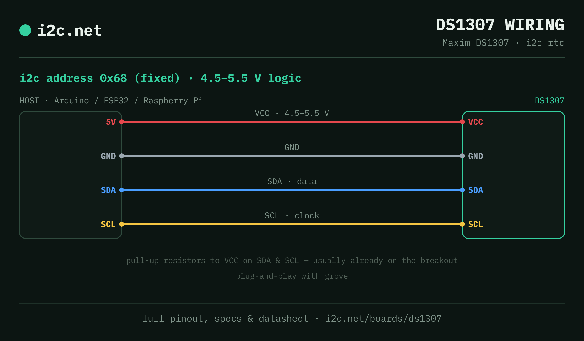
The DS1307 talks i2c at address 0x68. It runs at 4.5–5.5 V, so match your host's logic level — if your host is 5 V and a board on the bus is 3.3 V-only, add a level shifter. Use the compatibility checker to confirm the exact cable for your setup.
The address is fixed, so two DS1307s can't share a bus directly — the address-conflict guide covers the workarounds (multiplexer, second bus).
Wiring is the usual four: power, ground, SDA and SCL, plus pull-up resistors — almost always already fitted on the breakout. Nothing showing up? Run an i2c scanner first; if the bus is silent, the 7-step checklist finds it faster than guessing.
Ecosystems
Plug-together options for the DS1307
DS1307 breakouts ship with Grove — keyed 4-pin cables carrying power, ground, SDA and SCL, so there's nothing to solder and nothing to wire backwards. Chain it to the next board and keep going.
Running a mixed bench? Those ecosystems interoperate more than their marketing suggests — see every connector pairing for the cable or adapter you need, or the standards overview for how they compare.
Alternatives
Other real-time clock boards
Watch the bus
Boards that clash with the DS1307
These want an address the DS1307 also answers (0x68), so they can't share a bus with it untouched. If one is address-selectable, strap it elsewhere; if not, the conflict guide covers the multiplexer and second-bus routes, and the collision roundup explains why a scan won't warn you.
Get one
Questions
DS1307 i2c FAQ
What is the DS1307's i2c address?
The DS1307 sits at a fixed address of 0x68. It can't be changed, so two of them can't share one bus without a multiplexer or a second bus.
What voltage does the DS1307 run at?
Power it from 4.5–5.5 V — the DS1307 isn't specified for a 3.3 V supply. Its SDA/SCL inputs read logic-high from 2.2 V, so on a 3.3 V host (Pi, ESP32) run VCC at 5 V but pull the bus up to 3.3 V: no level shifter needed, and never pull a Pi's i2c up to 5 V.
Can I use two DS1307s on one i2c bus?
Not directly — every DS1307 answers to 0x68, so two on one bus would collide. Use a TCA9548A multiplexer to give each its own channel, or put the second one on a separate bus.
Does the DS1307 work with Grove?
Yes — DS1307 breakouts ship with Grove, so it plugs straight in with no soldering. Mixing ecosystems? The compatibility checker gives you the exact cable or adapter.
What should I watch out for with the DS1307?
Three traps. It's specified for a 4.5–5.5 V supply, not 3.3 V — power it from 5 V even on a Pi or ESP32. With no backup cell fitted, VBAT must be tied to ground (the datasheet's rule), or the clock won't run properly. And it sits at a fixed 0x68 — the DS3231's address and the MPU-6050's default — so a DS1307 plus an MPU-6050 collide until you move the IMU to 0x69.