How i2c works, byte by byte
i2c works by having one controller drive a shared clock (SCL) while addressing devices over a shared data line (SDA): a start condition opens the exchange, a 7-bit address picks the chip, and every byte is acknowledged before a stop condition frees the bus. Once you can read an i2c transaction the way you read a sentence, datasheets stop being scary and logic-analyzer captures become plain text.
The ground rules
Two wires, one grammar
i2c runs on SDA (data) and SCL (clock). Both are open-drain: any device may pull a line low, none may drive it high — resistors return the lines high. That one choice, made by Philips in 1982, is why almost everything below looks the way it does. The controller always generates the clock; data moves one bit per clock pulse, MSB first. And there's one golden timing rule that makes the whole protocol parseable: SDA may only change while SCL is low. An SDA change while SCL is high isn't data — it's punctuation.
That punctuation is the START condition (SDA falls while SCL is high — "everyone listen") and the STOP condition (SDA rises while SCL is high — "bus is free"). Between a start and a stop, the bus is busy and belongs to one conversation.
The physical layer
Open-drain, pull-ups and the wired-AND
Open-drain is worth stating precisely, because nearly every i2c quirk falls out of it. Each device can only switch a transistor to ground, pulling the line low; nothing drives it high. The lines idle high solely because external pull-up resistors tie them to the supply rail. The result is a wired-AND: if any device holds a line low, the whole bus reads low, and the line only rises once every device has released it.
That has a direct electrical consequence. A released line doesn't snap high — it charges through the pull-up against the bus's total capacitance, so the rise time follows the R–C product. The spec budgets 400 pF for a bus, and every device pin, connector and centimetre of trace spends some of it. Long chains push you toward stronger (lower-value) pull-ups, typically 2.2 kΩ–4.7 kΩ: too weak and the edges round off until data corrupts; too strong and a device can't sink enough current to reach a valid logic low. Sizing pull-ups against capacitance is the single most common thing engineers actually tune on an i2c bus — the pull-up guide has the full table, and cable length is the same constraint wearing a different hat.
Anatomy
One complete transaction
Step by step
The i2c address byte
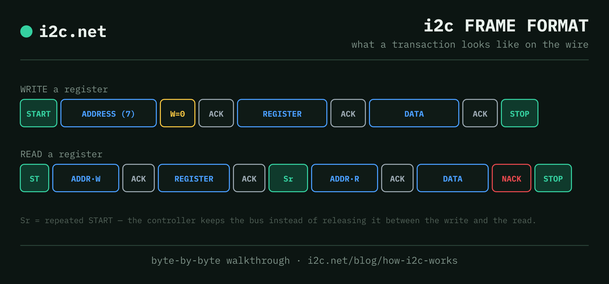
Every transaction opens with a start condition and then one byte that isn't data: the target's 7-bit address followed by the read/write bit — 0 to write, 1 to read. A BME280 at 0x76 being written to therefore appears on the wire as 0xEC (0x76 shifted left, write bit 0), and being read from as 0xED. That shift is the entire origin of the infamous "datasheet says 0xEC" confusion.
On the ninth clock pulse, the addressed device — if it exists, is powered, and heard its name — pulls SDA low: ACK. Silence (SDA stays high) is a NACK, and it's precisely what a bus scanner probes for at every address. A NACK isn't only "nobody's home", though — mid-transfer it also means "I'm finished" or "I can't accept more".
Seven bits gives 128 slots, but the spec reserves 16 of them — 0x00–0x07 and 0x78–0x7F — leaving 112 usable addresses, 0x08–0x77. That's why a scanner sweeps exactly that range; the address list breaks down what each reserved block is for.
10-bit i2c addressing
A 10-bit mode exists for buses that genuinely run out of room. It borrows one of those reserved patterns as an escape hatch: the controller sends 11110xx (0x78–0x7B) carrying the top two address bits, then a second byte with the low eight. Devices that only understand 7-bit addressing see an unfamiliar reserved address and stay quiet, so the two schemes coexist on one bus. In practice you'll rarely meet it — almost no hobby-grade part implements 10-bit addressing, and the usual answer to a crowded bus is a multiplexer instead.
Writing: pointer, then payload
Most chips are register machines: write a register pointer byte first, then the data for that register. Each byte gets its own ACK. Multi-byte writes usually auto-increment the pointer, so you can stream a whole configuration block in one transaction and finish with a stop.
Reading: the repeated start
Reading a register is a two-act play: first a short write to set the register pointer, then a read from the same address. Rather than stopping between the acts, the controller issues a repeated start (Sr) — a second start with no stop — keeping the bus locked so nothing can disturb the pointer in between. During the read, the roles flip: the target drives SDA while the controller keeps clocking, and the controller ACKs each byte it wants more after. The last byte gets a deliberate NACK — the polite way to say "done" — then stop.
Clock stretching: the target pushes back
The controller owns the clock — with one exception. A target that needs more time (an MCU-based sensor still preparing a sample) can hold SCL low after the controller tries to release it. Thanks to the wired-AND, the controller sees the clock still low and simply waits. That's clock stretching, and it's optional: plenty of chips never do it.
It matters because some hardware i2c peripherals implement it badly. The classic casualty is Sensirion's SCD30 CO2 sensor, which can stretch the clock for up to 150 ms — while the Raspberry Pi's controller hard-codes a far shorter timeout, so reads fail in ways no amount of rewiring fixes. (Its newer SCD4x siblings sidestep the whole problem by having you wait a fixed command-execution time instead.)
When two controllers collide
Because the lines are open-drain, multi-controller buses resolve themselves without a referee. Two controllers transmitting simultaneously will agree bit-for-bit until one outputs a 1 (releases SDA) while the other holds a 0 — the line reads 0, the would-be-1 sender knows it lost, and it backs off mid-byte with no corruption. The loser gives up on a bit the winner was already driving low, so nothing on the wire changes and the winner never even knows there was a race.
Their clocks merge the same way. Under clock synchronization, each controller's SCL edges wired-AND together, so whichever device holds the clock low longest sets the pace — the bus automatically runs at the speed of its slowest participant.
Where the i2c speed modes come from
Standard-mode is 100 kHz, Fast-mode 400 kHz (where most sensor work lives), Fast-mode Plus 1 MHz, High-speed 3.4 MHz — each faster grade tightening the rise-time budget those pull-up resistors must meet. There's also a one-way Ultra Fast-mode at 5 MHz, but it abandons the two things that define i2c — it swaps open-drain for push-pull and drops the ACK entirely — so it's write-only and rarely seen.
Every step up loops straight back to pull-up sizing and bus capacitance, which is why "make it faster" and "make the cable longer" are opposing forces. Full breakdown in speed modes. For most sensor work 100 kHz is plenty and maximally forgiving — if you're choosing between speed and reliability, this whole protocol was designed for the second one.
Why it matters
The failure modes stop being mysterious
Understood at this level, i2c's classic problems resolve into a short list of causes. A dead bus is usually a missing or mis-sized pull-up. A ghost or missing device is an address collision — or the 7-bit/8-bit confusion above. A sensor that works on a 3.3 V host but not a 5 V one is a level-shifting problem. Intermittent reads on a Raspberry Pi point at clock stretching. And a bus that works short but fails long is capacitance beating the pull-ups.
The two wires are simple. The electrical contract behind them is what you actually engineer around — and when something breaks, the 7-step checklist walks that contract in order.
Seeing the machinery also explains i2c's limits. Every byte costs nine clocks plus addressing overhead, and the whole thing rides on resistors dragging a capacitive line high — which is precisely why it loses to SPI the moment you need bandwidth, and why UART is the better answer for a single device at the end of a long cable. All three side by side if you're still choosing.
Worth knowing how far this reaches: the exact protocol above is what your laptop's touchpad speaks to its chipset — that's what the i2c HID Device entry in Windows Device Manager is. Same START/STOP framing, same addressing, same pull-ups; Microsoft just wraps a report model on top.
Questions
Protocol FAQ
What do SDA and SCL actually carry?
SCL carries the clock, always generated by the controller. SDA carries everything else — addresses, data and acknowledgements — one bit per clock pulse, most significant bit first. Data on SDA may only change while SCL is low; a change while SCL is high is, by definition, a start or stop condition.
What is the difference between ACK and NACK?
After every 8 bits, the receiver gets the 9th clock pulse to answer: pulling SDA low is an ACK (got it, continue), leaving it high is a NACK. A NACK after an address byte means no device answered — that's exactly what a bus scanner listens for. A controller also deliberately NACKs the final byte of a read to say 'that's enough.'
What is a repeated start and why not just stop and start again?
A repeated start is a second start condition without a stop in between. It chains the two halves of a register read (write the register pointer, then read the data) into one unbroken transaction, so on a multi-controller bus nobody can grab the bus between the halves and change the register pointer under you.
Who wins when two controllers transmit at once?
Arbitration falls out of the open-drain wiring for free: both keep transmitting until one sends a 1 (releases SDA) but reads the line as 0 — someone else is holding it low. That controller silently loses, stops driving, and retries later. The winner never notices, and no data is corrupted.
Is i2c the same thing as SMBus or TWI?
Close cousins. TWI is just Atmel's trademark-dodging name for i2c — treat it as identical. SMBus is a stricter subset used on PC motherboards: lower speed ceiling, fixed logic thresholds and a 35 ms limit on clock stretching. Most sensors labelled either way interoperate fine at 100 kHz.
What is the wired-AND on an i2c bus?
Because SDA and SCL are open-drain, a device can only pull a line low — never drive it high. So if any device holds a line low the whole bus reads low, and the line only rises once every device has released it. That behaviour is what makes address collisions, arbitration and clock stretching all work the way they do.
Does i2c support more than 7-bit addresses?
Yes — a 10-bit mode exists. It uses the reserved 11110xx pattern (0x78–0x7B) as an escape sequence carrying the top two address bits, followed by a second byte with the low eight. 7-bit-only devices ignore it, so both can share a bus. Very few hobby parts implement it; a multiplexer is the usual answer to a crowded bus.