TPIC2810 — i2c address & wiring
8-bit i2c LED / low-side driver — latch eight open-drain outputs over two wires.
Key facts
TPIC2810 at a glance
| i2c address | 0x600x610x620x630x640x650x660x67 address-selectable via pins/jumpers |
|---|---|
| Logic voltage | 3–5.5 V |
| Type | driver |
| Part | TI TPIC2810 |
| Ships with | generic modules — plain 0.1″ headers, no connector system |
The chip
What the TI TPIC2810 actually is
Eight-bit low-side driver with an i2c interface: the host writes a byte and the chip latches eight open-drain outputs to switch LEDs or other resistive loads, each rated to roughly 210 mA. A hardcoded 1100 group ID plus three address pins (A0–A2) put up to eight devices — 0x60 through 0x67 — on one bus.
Watch out: The address is widely quoted as just 0x60–0x63, but the three address pins (A0–A2) span the full 0x60–0x67 — eight devices on a bus, not four. If a scan turns one up at 0x64–0x67, that's why. Note too that it's a low-side driver: the outputs sink current, so LEDs wire from your load rail through a resistor to each output pin, not the other way round.
Wiring
How to connect the TPIC2810
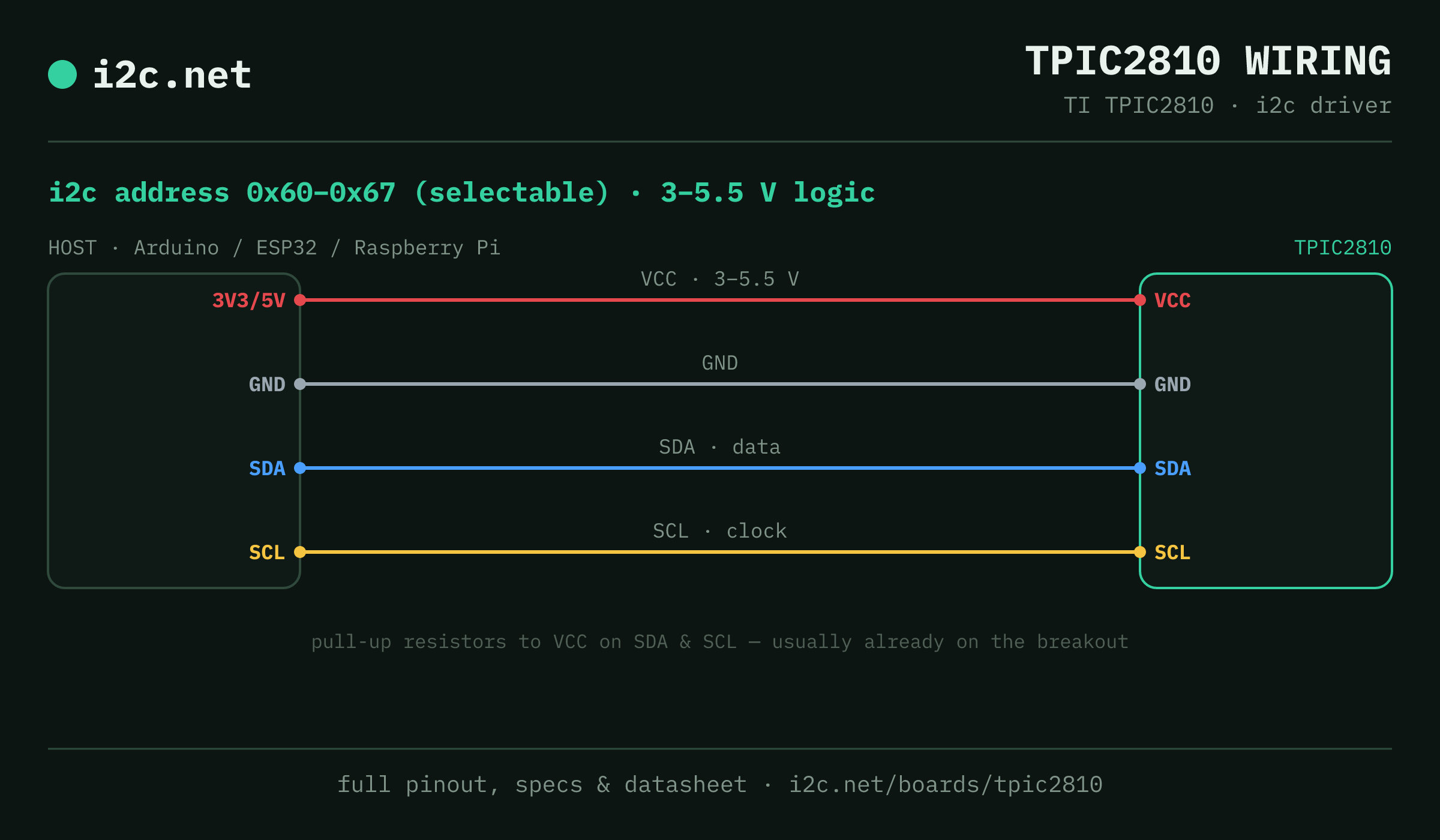
The TPIC2810 talks i2c at address 0x60 (up to 8 selectable addresses, handy when you need more than one on the same bus). It runs at 3–5.5 V, so match your host's logic level — if your host is 5 V and a board on the bus is 3.3 V-only, add a level shifter. Use the compatibility checker to confirm the exact cable for your setup.
Because the address is selectable, you can run several TPIC2810 boards on one bus by setting each to a different address — no extra wiring beyond the shared SDA/SCL.
Wiring is the usual four: power, ground, SDA and SCL, plus pull-up resistors — almost always already fitted on the breakout. Nothing showing up? Run an i2c scanner first; if the bus is silent, the 7-step checklist finds it faster than guessing.
Alternatives
Other i2c drivers
Watch the bus
Boards that clash with the TPIC2810
These want addresses the TPIC2810 also answers (0x60, 0x62), so they can't share a bus with it untouched. If one is address-selectable, strap it elsewhere; if not, the conflict guide covers the multiplexer and second-bus routes, and the collision roundup explains why a scan won't warn you.
Questions
TPIC2810 i2c FAQ
What is the TPIC2810's i2c address?
The TPIC2810 uses 0x60 or 0x61 or 0x62 or 0x63 or 0x64 or 0x65 or 0x66 or 0x67, selected with an address pin or solder jumper on the board. If a scan turns up something unexpected, our i2c address list names the usual suspect for every address.
What voltage does the TPIC2810 run at?
The 3–5.5 V figure is the logic / i2c supply (VCC). The eight open-drain outputs switch their own load rail — LEDs or other low-side loads — independent of that VCC.
Can I use two TPIC2810s on one i2c bus?
Yes — set each one to a different address (0x60, 0x61, 0x62, 0x63, 0x64, 0x65, 0x66, 0x67) using its address pin or jumper, then wire both to the same SDA/SCL. That gives you up to 8 on a single bus before you need a multiplexer.
Does the TPIC2810 come as a plug-together breakout?
Not in the mainstream connector ecosystems — TPIC2810 modules are generic boards with 0.1″ headers, so you'll be soldering headers and running jumper wires to SDA, SCL, power and ground.
What should I watch out for with the TPIC2810?
The address is widely quoted as just 0x60–0x63, but the three address pins (A0–A2) span the full 0x60–0x67 — eight devices on a bus, not four. If a scan turns one up at 0x64–0x67, that's why. Note too that it's a low-side driver: the outputs sink current, so LEDs wire from your load rail through a resistor to each output pin, not the other way round.