Si5351A — i2c address & wiring
Three independent clock outputs from 8 kHz to 160 MHz, programmed over i2c.
Key facts
Si5351A at a glance
| i2c address | 0x60 fixed address |
|---|---|
| Logic voltage | 2.5–3.6 V |
| Type | clock |
| Part | Skyworks Si5351A |
| Ships with | generic modules — plain 0.1″ headers, no connector system |
The chip
What the Skyworks Si5351A actually is
PLL clock generator synthesizing three independent square-wave outputs from one 25/27 MHz crystal — roughly 8 kHz to 160 MHz with fine fractional tuning. The standard way to give a project a programmable oscillator: ham-radio VFOs, clock experiments, driving ADCs or retro CPUs, all retuned live over i2c.
Watch out: Two things bite. Every board needs per-crystal calibration — the reference is routinely tens of ppm off, which matters at RF. And many cheap CJMCU-style boards ship the MS5351M, a register-compatible clone with measurably worse phase noise: fine for digital clocking, audible in radio work. The chip is 3.3 V-only; 5 V hosts need level shifting.
Wiring
How to connect the Si5351A
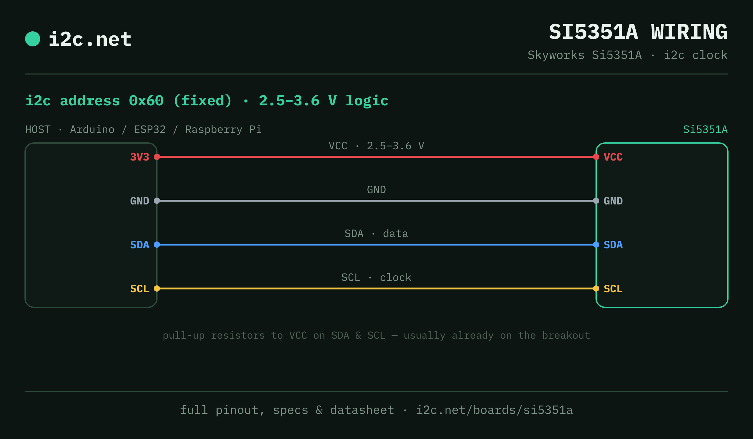
The Si5351A talks i2c at address 0x60. It runs at 2.5–3.6 V, so match your host's logic level — if your host is 5 V and a board on the bus is 3.3 V-only, add a level shifter. Use the compatibility checker to confirm the exact cable for your setup.
The address is fixed, so two Si5351As can't share a bus directly — the address-conflict guide covers the workarounds (multiplexer, second bus).
Wiring is the usual four: power, ground, SDA and SCL, plus pull-up resistors — almost always already fitted on the breakout. Nothing showing up? Run an i2c scanner first; if the bus is silent, the 7-step checklist finds it faster than guessing.
Watch the bus
Boards that clash with the Si5351A
These want an address the Si5351A also answers (0x60), so they can't share a bus with it untouched. If one is address-selectable, strap it elsewhere; if not, the conflict guide covers the multiplexer and second-bus routes, and the collision roundup explains why a scan won't warn you.
Get one
Questions
Si5351A i2c FAQ
What is the Si5351A's i2c address?
The Si5351A sits at a fixed address of 0x60. It can't be changed, so two of them can't share one bus without a multiplexer or a second bus.
What voltage does the Si5351A run at?
2.5–3.6 V logic. It's 2.5 V-only — driving it straight from a 5 V Arduino risks damage, so level-shift first.
Can I use two Si5351As on one i2c bus?
Not directly — every Si5351A answers to 0x60, so two on one bus would collide. Use a TCA9548A multiplexer to give each its own channel, or put the second one on a separate bus.
Does the Si5351A come as a plug-together breakout?
Not in the mainstream connector ecosystems — Si5351A modules are generic boards with 0.1″ headers, so you'll be soldering headers and running jumper wires to SDA, SCL, power and ground.
What should I watch out for with the Si5351A?
Two things bite. Every board needs per-crystal calibration — the reference is routinely tens of ppm off, which matters at RF. And many cheap CJMCU-style boards ship the MS5351M, a register-compatible clone with measurably worse phase noise: fine for digital clocking, audible in radio work. The chip is 3.3 V-only; 5 V hosts need level shifting.