HTU21D — i2c address & wiring
Digital humidity and temperature sensor at a fixed — and crowded — 0x40.
Key facts
HTU21D at a glance
| i2c address | 0x40 fixed address |
|---|---|
| Logic voltage | 1.5–3.6 V |
| Type | sensor |
| Part | TE Connectivity HTU21D(F) |
| Ships with | generic modules — plain 0.1″ headers, no connector system |
| Datasheet | TE Connectivity HTU21D(F) — manufacturer documentation ↗ |
The chip
What the TE Connectivity HTU21D(F) actually is
Calibrated digital relative-humidity and temperature sensor with selectable measurement resolution and an on-chip heater for diagnostics; the HTU21DF version adds a PTFE filter membrane that keeps dust and water off the sensing element. Supply runs 1.5–3.6 V, 3 V recommended.
Watch out: 0x40 is crowded and the HTU21D can't move: it's also the default for the INA219 and INA260 power monitors and the PCA9685 servo driver. Pair it with one of those and the other part has to change address — or the HTU21D goes on its own bus or behind a multiplexer.
Wiring
How to connect the HTU21D
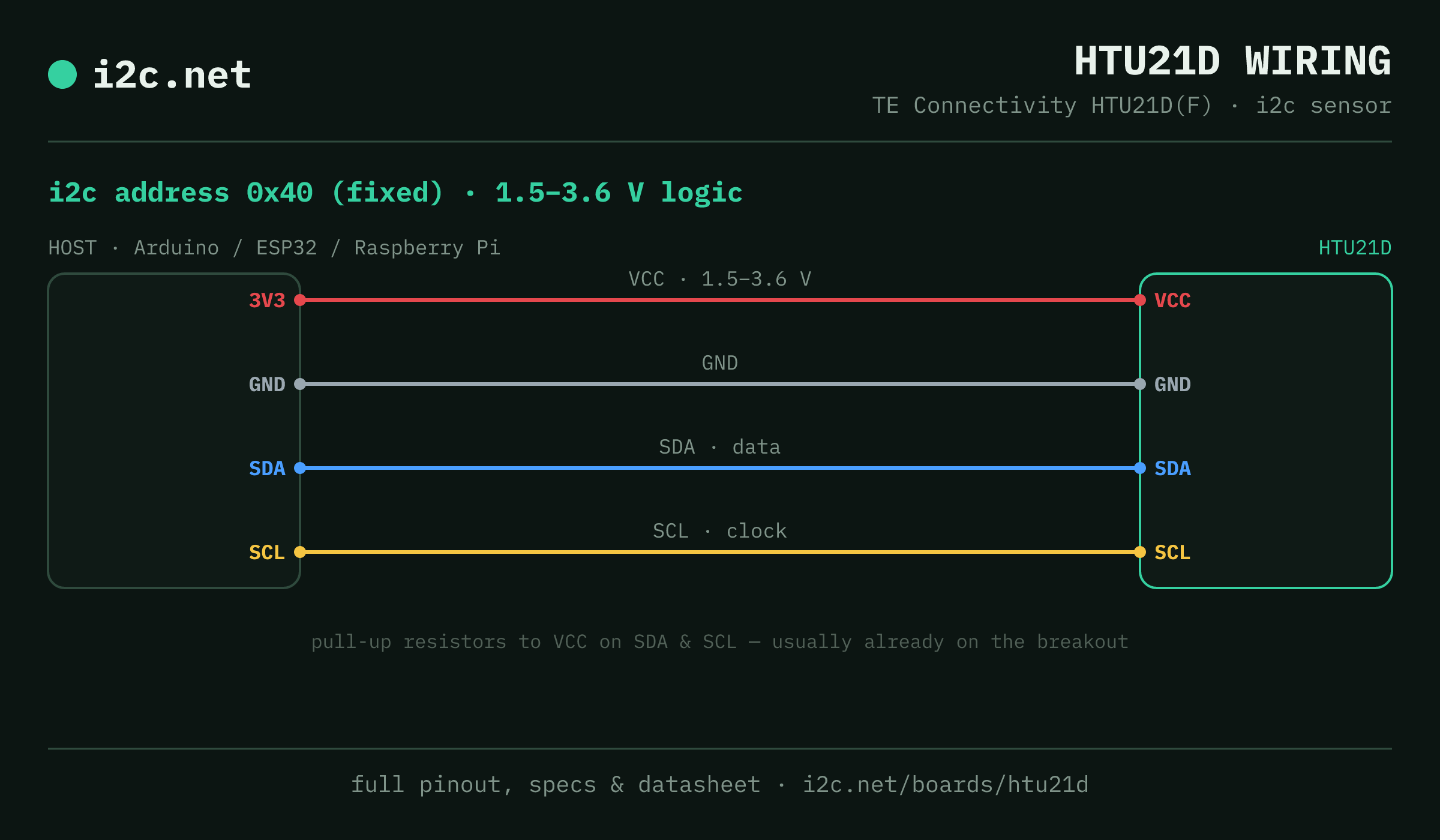
The HTU21D talks i2c at address 0x40. It runs at 1.5–3.6 V, so match your host's logic level — if your host is 5 V and a board on the bus is 3.3 V-only, add a level shifter. Use the compatibility checker to confirm the exact cable for your setup.
The address is fixed, so two HTU21Ds can't share a bus directly — the address-conflict guide covers the workarounds (multiplexer, second bus).
Wiring is the usual four: power, ground, SDA and SCL, plus pull-up resistors — almost always already fitted on the breakout. Nothing showing up? Run an i2c scanner first; if the bus is silent, the 7-step checklist finds it faster than guessing.
Alternatives
Other environmental boards
Watch the bus
Boards that clash with the HTU21D
These want an address the HTU21D also answers (0x40), so they can't share a bus with it untouched. If one is address-selectable, strap it elsewhere; if not, the conflict guide covers the multiplexer and second-bus routes, and the collision roundup explains why a scan won't warn you.
Get one
Questions
HTU21D i2c FAQ
What is the HTU21D's i2c address?
The HTU21D sits at a fixed address of 0x40. It can't be changed, so two of them can't share one bus without a multiplexer or a second bus.
What voltage does the HTU21D run at?
The sensor is a 1.5–3.6 V part and must not see 5 V on its supply or i2c pins. Plenty of modules add a regulator and level shifting for 5 V hosts — check yours before wiring it to an Arduino Uno.
Can I use two HTU21Ds on one i2c bus?
Not directly — every HTU21D answers to 0x40, so two on one bus would collide. Use a TCA9548A multiplexer to give each its own channel, or put the second one on a separate bus.
Does the HTU21D come as a plug-together breakout?
Not in the mainstream connector ecosystems — HTU21D modules are generic boards with 0.1″ headers, so you'll be soldering headers and running jumper wires to SDA, SCL, power and ground.
What should I watch out for with the HTU21D?
0x40 is crowded and the HTU21D can't move: it's also the default for the INA219 and INA260 power monitors and the PCA9685 servo driver. Pair it with one of those and the other part has to change address — or the HTU21D goes on its own bus or behind a multiplexer.