TSL2561 — i2c address & wiring
Lux sensor with broadband and infrared photodiodes, close to human-eye response.
Key facts
TSL2561 at a glance
| i2c address | 0x290x390x49 address-selectable via pins/jumpers |
|---|---|
| Logic voltage | 2.7–3.6 V |
| Type | sensor |
| Part | ams TSL2561 |
| Ships with | Grove |
| Datasheet | ams TSL2561 — manufacturer documentation ↗ |
The chip
What the ams TSL2561 actually is
Light-to-digital converter with one broadband (visible plus infrared) photodiode and one infrared-only photodiode; combining the two channels gives an illuminance figure that approximates the human eye's response. The ADDR SEL pin is three-state — GND for 0x29, floating for 0x39, VDD for 0x49. Supply runs 2.7–3.6 V.
Watch out: The address pin has three states, not two, and floating is a valid one (0x39) — so a module with an unconnected ADDR pad isn't broken. At 0x29 it collides with the VL53L0X, VL53L1X and TCS34725; float ADDR or tie it to VDD to move it.
Wiring
How to connect the TSL2561
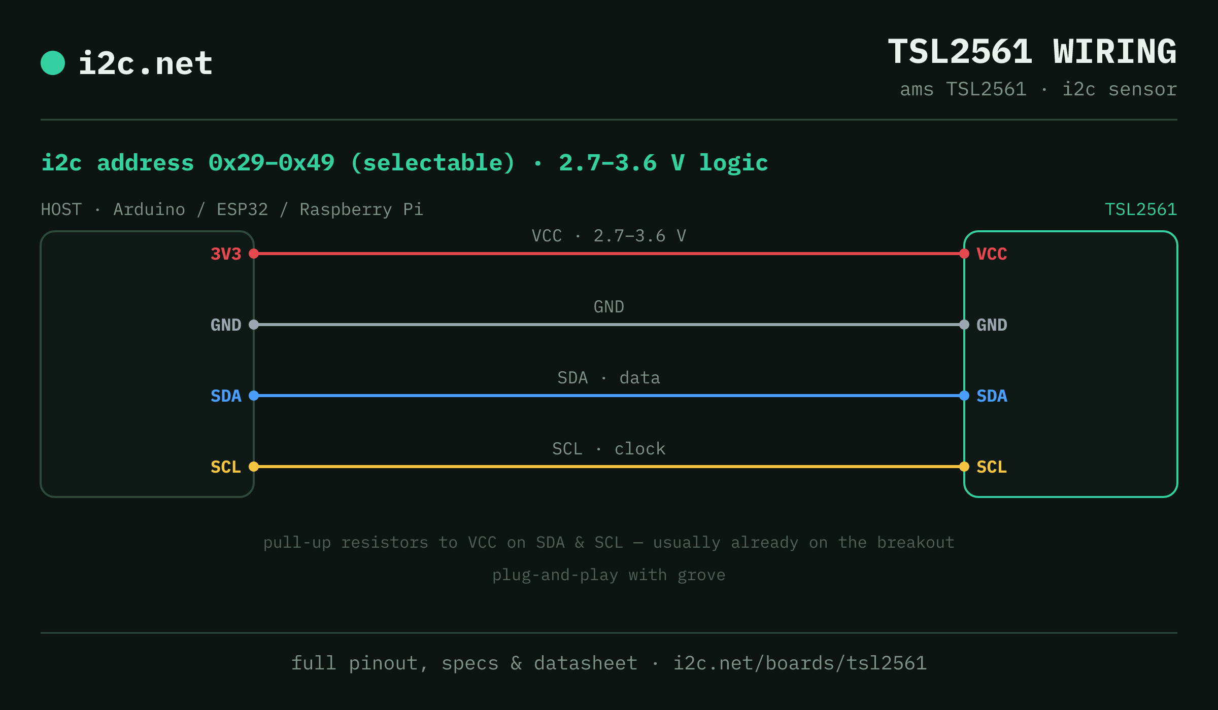
The TSL2561 talks i2c at address 0x29 (up to 3 selectable addresses, handy when you need more than one on the same bus). It runs at 2.7–3.6 V, so match your host's logic level — if your host is 5 V and a board on the bus is 3.3 V-only, add a level shifter. Use the compatibility checker to confirm the exact cable for your setup.
Because the address is selectable, you can run several TSL2561 boards on one bus by setting each to a different address — no extra wiring beyond the shared SDA/SCL.
Wiring is the usual four: power, ground, SDA and SCL, plus pull-up resistors — almost always already fitted on the breakout. Nothing showing up? Run an i2c scanner first; if the bus is silent, the 7-step checklist finds it faster than guessing.
Ecosystems
Plug-together options for the TSL2561
TSL2561 breakouts ship with Grove — keyed 4-pin cables carrying power, ground, SDA and SCL, so there's nothing to solder and nothing to wire backwards. Chain it to the next board and keep going.
Running a mixed bench? Those ecosystems interoperate more than their marketing suggests — see every connector pairing for the cable or adapter you need, or the standards overview for how they compare.
Alternatives
Other light boards
Watch the bus
Boards that clash with the TSL2561
These want addresses the TSL2561 also answers (0x29, 0x39, 0x49), so they can't share a bus with it untouched. If one is address-selectable, strap it elsewhere; if not, the conflict guide covers the multiplexer and second-bus routes, and the collision roundup explains why a scan won't warn you.
Get one
Questions
TSL2561 i2c FAQ
What is the TSL2561's i2c address?
The TSL2561 uses 0x29 or 0x39 or 0x49, selected with an address pin or solder jumper on the board. If a scan turns up something unexpected, our i2c address list names the usual suspect for every address.
What voltage does the TSL2561 run at?
The sensor runs from 2.7–3.6 V and isn't 5 V tolerant. Many modules add a regulator and level shifting for 5 V hosts — check yours before wiring it to a 5 V Arduino.
Can I use two TSL2561s on one i2c bus?
Yes — set each one to a different address (0x29, 0x39, 0x49) using its address pin or jumper, then wire both to the same SDA/SCL. That gives you up to 3 on a single bus before you need a multiplexer.
Does the TSL2561 work with Grove?
Yes — TSL2561 breakouts ship with Grove, so it plugs straight in with no soldering. Mixing ecosystems? The compatibility checker gives you the exact cable or adapter.
What should I watch out for with the TSL2561?
The address pin has three states, not two, and floating is a valid one (0x39) — so a module with an unconnected ADDR pad isn't broken. At 0x29 it collides with the VL53L0X, VL53L1X and TCS34725; float ADDR or tie it to VDD to move it.