TFmini Plus — i2c address & wiring
0.1–12 m time-of-flight lidar that speaks UART out of the box and i2c on request.
Key facts
TFmini Plus at a glance
| i2c address | 0x10 fixed address |
|---|---|
| Logic voltage | 4.5–6 V |
| Type | sensor |
| Part | Benewake TFmini Plus |
| Ships with | generic modules — plain 0.1″ headers, no connector system |
| Datasheet | Benewake TFmini Plus — manufacturer documentation ↗ |
The chip
What the Benewake TFmini Plus actually is
Compact ToF lidar ranging 0.1–12 m at up to 1000 Hz with centimetre-level resolution, in an IP65 housing. It carries both UART and i2c (default address 0x10) on the same cable — the active mode is switched by a configuration command and persists across power cycles.
Watch out: It ships in UART mode and stays invisible to an i2c scan until you send the interface-switch command once over serial — which trips up nearly everyone's first attempt. Two more: a hard reset won't put it back to serial afterwards, only an explicit set-serial-mode command does; and its fixed 0x10 is the same address as the VEML7700 light sensor, so that pair needs a multiplexer.
Wiring
How to connect the TFmini Plus
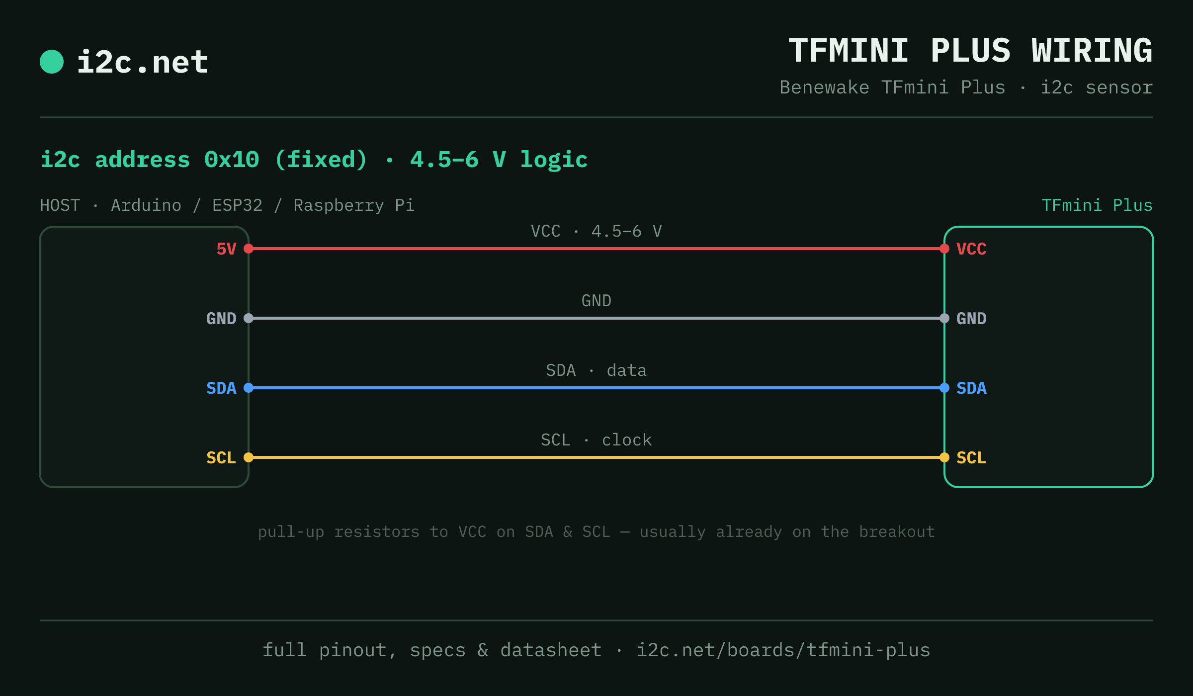
The TFmini Plus talks i2c at address 0x10. It runs at 4.5–6 V, so match your host's logic level — if your host is 5 V and a board on the bus is 3.3 V-only, add a level shifter. Use the compatibility checker to confirm the exact cable for your setup.
The address is fixed, so two TFmini Pluss can't share a bus directly — the address-conflict guide covers the workarounds (multiplexer, second bus).
Wiring is the usual four: power, ground, SDA and SCL, plus pull-up resistors — almost always already fitted on the breakout. Nothing showing up? Run an i2c scanner first; if the bus is silent, the 7-step checklist finds it faster than guessing.
Go deeper
Guides covering the TFmini Plus
Alternatives
Other distance boards
Watch the bus
Boards that clash with the TFmini Plus
These want an address the TFmini Plus also answers (0x10), so they can't share a bus with it untouched. If one is address-selectable, strap it elsewhere; if not, the conflict guide covers the multiplexer and second-bus routes, and the collision roundup explains why a scan won't warn you.
Get one
Questions
TFmini Plus i2c FAQ
What is the TFmini Plus's i2c address?
The TFmini Plus sits at a fixed address of 0x10. It can't be changed, so two of them can't share one bus without a multiplexer or a second bus.
What voltage does the TFmini Plus run at?
Power comes from 5 V (4.5–6 V), but the UART/i2c lines are 3.3 V logic — data wires straight to a Pi or ESP32 with no level shifter; just feed the supply pin an actual 5 V rail.
Can I use two TFmini Pluss on one i2c bus?
Not directly — every TFmini Plus answers to 0x10, so two on one bus would collide. Use a TCA9548A multiplexer to give each its own channel, or put the second one on a separate bus.
Does the TFmini Plus come as a plug-together breakout?
Not in the mainstream connector ecosystems — TFmini Plus modules are generic boards with 0.1″ headers, so you'll be soldering headers and running jumper wires to SDA, SCL, power and ground.
What should I watch out for with the TFmini Plus?
It ships in UART mode and stays invisible to an i2c scan until you send the interface-switch command once over serial — which trips up nearly everyone's first attempt. Two more: a hard reset won't put it back to serial afterwards, only an explicit set-serial-mode command does; and its fixed 0x10 is the same address as the VEML7700 light sensor, so that pair needs a multiplexer.